
Fiber Optic Plate Manufacturing: From Glass Formulation to Precision Fiber Drawing
How do fiber optic plates capture sharp images in near darkness? The answer lies in a tightly controlled process that starts with glass chemistry and ends with fiber drawing at the micron level. Industry leaders like HONSUN have refined this technology, making special parts such as the Bending Fiber Optic Plate for 360° cameras and vehicle-mounted systems. This guide walks you through each stage, showing how material science, precision engineering, and strict quality control work together in fiber optic manufacturing. You will see how each step in making affects the final optical performance. Knowing this process shows why fiber optic parts are vital in aerospace, medical imaging, and night vision uses.
Key Takeaways
· Fiber optic plates begin with pure glass and exact chemistry. This prepares the way for sharp pictures.
· Drawing fibers with careful control keeps them uniform. This step is key for clear pictures.
· Stacking and fusing fibers must be precise. This makes the plate work as one piece.
· Quality tests check how clear the image is and how strong the plate is. These tests make sure the plates can handle harsh environments.
· HONSUN's bending plates give clear images and use light well. They fit advanced imaging needs.
Glass Formulation for Fiber Optic Plates

Selecting Core and Cladding Materials
You start with very pure raw materials. Silica is the main ingredient, and dopants fine-tune the refractive index. The dopants you add change the refractive index with great accuracy. This lets you set the numerical aperture for your exact needs. HONSUN uses advanced glass recipes to keep light loss low and heat stability high. This matters for their bending fiber optic plate. Picking the right materials directly affects how well the final product performs optically.
The gap in refractive index between core and cladding sets the numerical aperture (NA). For step-index fibers, the formula is:
A bigger index gap raises the NA. This lets the fiber carry light even when bent into a tighter curve. That trait is key for plates that steer images in multiple directions. HONSUN's bending fiber optic plate uses this idea to move light with high efficiency.
These index gap effects matter for your design:
· A bigger index gap lets the fiber stay single-mode across a wider set of wavelengths.
· A bigger index gap lets the fiber guide light even when bent to a smaller radius.
So you can get sharp images and strong light flow in your plate.
Heat stability of the glass is also vital. HONSUN's recipes make sure the glass can handle the extreme heat during fiber drawing without warping. That stability keeps the exact core-cladding shape needed for clear imaging.
Melting and Homogenization Process
Careful temperature control stops flaws and keeps glass quality even. This is a key step in making fiber optics.
Homogenization removes bubbles and striae from the melt. Methods include adjusting pour temperature and mixing. The table below shows what each method achieves.
Technique | Outcome on Striae/Bubbles |
Optimized pour temperature and mixing | Clear glass with very few striae; light transmission above 98% from 580 nm to 1100 nm |
Unoptimized melt-quench settings | Wide striae locked into the glass, causing major loss of light transmission |
Higher melt pour temperature | Likely to shrink both the number and size of harmful striae; polished preform showed no visible striae inside |
These methods make the glass melt uniform. That uniformity is essential for fiber optic performance. The production process must manage these settings to create top-quality optical parts. HONSUN uses optimized pour temperatures and mixing to get clear glass with minimal striae. This keeps light transmission high in their finished products.
Preform Fabrication: Building the Fiber Optic Structure
Creating the Core Rod and Cladding Tube
You start preform fabrication with two exact glass parts: the core rod and the cladding tube. The core rod holds glass with a higher refractive index that guides light. The cladding tube wraps around it with lower index glass. This creates the optical edge that keeps light inside. This rod-in-tube setup forms the base of every fiber optic plate you will make.
Manufacturing tolerances matter a lot at this point. Standard substrate tubes, which become core rods, range from 15 to 40 mm in outer diameter. Telecom-scale operations may use tubes up to 60 mm. Jacket tubes for cladding reach 20 to 200 mm in outer diameter. Both tube types need strict specs:
· Outer and inner diameter tolerance of ±0.1 mm
· Concentricity greater than 98%
· Ovality below 0.5% of outer diameter (below 0.3% for high-precision grades)
· Straightness within 0.5 mm per meter
These numbers decide how evenly light will move through your finished plate. A slight ovality in the cladding tube creates uneven wall thickness. That unevenness bends the image path. You cannot fix this flaw later in the process.
HONSUN uses special multi-stage packaging methods during this assembly phase. Each stage lines up the core rod and cladding tube with micron-level accuracy. This careful alignment ensures a uniform core-to-cladding ratio across the whole preform length. That uniformity directly supports the high resolution you need for tough imaging tasks.
Collapsing into a Solid Preform
Once you assemble the rod and tube, you heat the pair to its softening point. The glass starts to flow. The cladding tube collapses inward, making firm contact with the core rod. This step removes any air gap between the two glass layers. An air gap would reflect light and cut transmission efficiency.
HONSUN uses low-temperature glass welding methods during this collapse. Lower temperatures reduce thermal stress inside the glass structure. Less stress means fewer micro-cracks and inclusions. The result is a solid preform with clean optical surfaces.
The collapsed preform now has the exact refractive index profile you need. You will later draw this preform into hundreds of separate fibers. Each fiber keeps the precise core-cladding shape set during this fabrication stage. For special products like the bending fiber optic plate, this shape accuracy becomes even more vital. The plate must redirect images in different directions without adding distortion.
Quality checks at this stage verify the preform's size and optical clarity. You measure the collapsed diameter along its full length. You look for bubbles, striae, or any leftover interface flaws. Only preforms that pass these checks move forward to the drawing tower. This discipline in preform fabrication sets premium fiber optic manufacturing apart from ordinary glass processing.
Precision Fiber Drawing for Optical Fibers
Heating, Neck-Down, and Tension Control
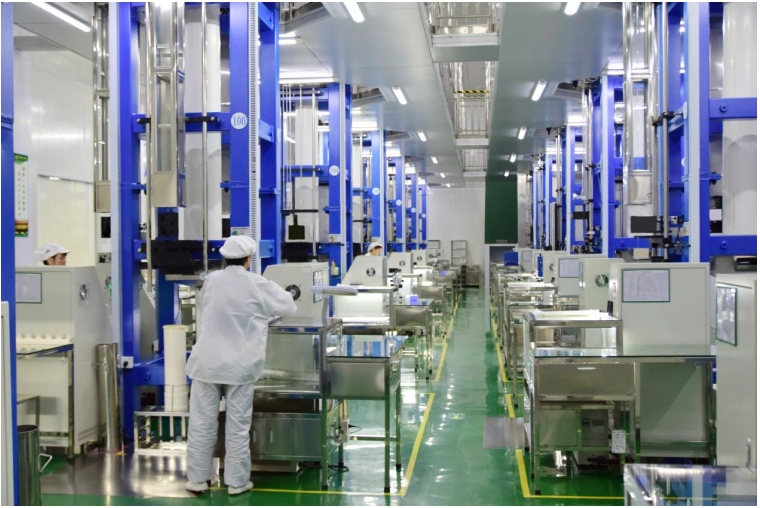
You place the solid preform at the top of a fiber drawing tower. The tower heats the preform until it softens. The hot glass starts to flow, and gravity pulls a thin thread downward. This area is the neck-down zone, where the preform shrinks from centimeters wide to a thin fiber. You adjust the pull speed and heat to keep the core-to-cladding ratio exactly as planned. Any error here creates optical flaws that cannot be fixed later.
Tension control is key in this step. The force used to pull the fiber shapes its strength and evenness. More draw tension boosts breaking strength but lowers elongation. The table below shows this link.
HONSUN's draw towers achieve micrometer-level diameter control. This precision lets you make consistent fibers for tough products like the Bending Fiber Optic Plate, which uses a fiber size of 100um. The fiber drawing process at HONSUN keeps tight tolerances along the whole fiber length, ensuring uniform optical properties across every batch.
Real-Time Diameter Monitoring and Coating
As the fiber leaves the neck-down region, you measure its diameter in real time. Laser-based gauges capture the diameter at several points along the fiber path. The data feeds back to the draw tower controls, which adjust the pull speed right away to fix any error. This closed-loop system keeps the fiber diameter within a micron of the target value.
After diameter monitoring, you apply protective coatings. The bare glass fiber is fragile and needs quick protection. You use a dual-layer optical fiber coatings system. The table below shows the two layers.
The application process is fast and exact. The fiber passes through a pressurized die that applies the primary acrylate. It then enters a second die for the harder secondary layer. UV chambers cure both layers using mercury lamps or LEDs. A nitrogen purge stops oxygen from blocking the cure. The result is a standard dual-coated fiber with a strong protective jacket.
These fiber optic coatings serve many roles. The soft inner layer cushions the glass against micro-bending. The hard outer layer resists abrasion and moisture. Together, they shield the fiber during later handling and assembly. HONSUN applies these optical fiber coatings with precision to ensure steady quality. The fiber optic coatings system is a vital part of modern manufacturing for fiber optic components. The whole manufacturing process, from preform to coated fiber, must be tightly controlled. The fiber drawing process at HONSUN shows this level of control. Proper optical fiber coatings extend the life and reliability of the finished product. These optical fiber coatings also guard against environmental factors during operation.
Plate Assembly: Stacking, Fusing, and Cutting Fiber Optic Plates
Stacking Fibers into a Coherent Bundle
You now have hundreds of individual coated fibers. Your next task transforms these separate strands into a single, ordered structure. This stage defines the difference between random light guides and true imaging plates.
You begin by cutting the drawn fibers into equal lengths. Each piece must match the others within tight tolerances. You then arrange these fibers into a precise hexagonal or rectangular array. The arrangement must preserve the exact spatial relationship from input to output. Any fiber that shifts position creates a distorted pixel in the final image.
For standard plates, you stack fibers in straight, parallel rows. But HONSUN's bending fiber optic plate demands more complex alignment. This product redirects images in different directions for 360° camera systems and vehicle-mounted setups. You must angle each fiber progressively across the bundle. The angle changes gradually from one edge to the other. This careful positioning lets the finished plate bend the image path without breaking the visual continuity.
You also insert extra mural absorbers (EMA) between the active fibers during stacking. These dark glass strands absorb stray light that leaks from one fiber to another. Without EMA, light crosstalk would blur the image and cut contrast. The absorber placement requires the same precision as the fiber positioning itself.
The stacking process happens under magnification. You use alignment fixtures that hold each fiber layer in place. You check the bundle periodically to confirm the pattern has not drifted. For the bending plate, you verify the angle progression at multiple checkpoints. This inspection prevents errors from compounding as you add more layers.
Fusing and Slicing into Fiber Optic Plates
Once you complete the stack, you move the bundle to a fusing furnace. You heat the assembly to the glass softening point. Pressure applied evenly across the stack forces the individual fibers to bond together. The cladding glass flows slightly, filling any microscopic gaps between fibers. This fusion creates a solid block with no air pockets or voids.
Temperature control during fusing demands precision. Too little heat leaves weak bonds between fibers. Too much heat causes the core glass to deform, changing the optical path. HONSUN's low-temperature glass welding techniques reduce thermal stress during this step. Lower stress means fewer micro-cracks and better long-term reliability.
After cooling, you have a solid fused block called a boule. You now slice this boule into thin wafers using diamond cutting tools. Each slice becomes one fiber optic plate. The cutting angle determines the plate's final optical characteristics. For the bending plate, you cut at an angle that matches the intended image redirection.
You then grind and polish both surfaces of each slice. The polishing process removes surface scratches and brings the plate to its final thickness. Surface quality directly affects resolution and transmission efficiency. A rough surface scatters light and degrades image sharpness.
The finished plate undergoes final dimensional checks. You verify thickness, flatness, and parallelism. For HONSUN's bending plate, you also confirm the bend angle matches the specification. This manufacturing sequence transforms loose fibers into precise optical components ready for integration into imaging systems.
Quality Control in Fiber Optic Plate Manufacturing
Mechanical and Environmental Reliability
Good optics do not matter if the plate breaks under stress. You test mechanical strength by heating and cooling samples between 20°C and 300°C. The thermal expansion coefficient of (87±2)×10⁻⁷/℃ tells you how much the glass grows when hot. Plates that expand unevenly get tiny cracks that scatter light and make images worse. HONSUN uses low-temperature glass welding during manufacturing to reduce these internal stresses. This creates plates that survive many heating cycles without splitting.
Environmental testing also checks the surface. You expose plates to humidity, temperature extremes, and shaking. The optical fiber coatings added during drawing protect the glass first. These optical fiber coatings stop moisture from getting in and hurting the surface over time. The two-layer system—a soft inner coat and a hard outer layer—absorbs shock and resists scratching. Without proper optical fiber coatings, even the best glass would fail early in tough aerospace or marine settings. You also check that the fiber optic coatings stay strong after the fusing and cutting steps, since these steps put the material under a lot of heat and stress. Consistent quality control across every batch ensures each plate you get meets the same high standards, whether it goes to a medical device maker or a satellite builder.
Now you have seen the whole process of making fiber optic plates, from glass formulation to precision fiber drawing to final assembly. Each step changes how the plate works with light. Glass purity decides how much light gets through. Preform accuracy sets how sharp the picture can be. Controlling the drawing makes all fibers the same. Fusing and polishing affect how long the plate lasts and how clear the image is.
HONSUN is very good at every step of this fiber optic manufacturing process.
Do you want to see this technology in action? Book a factory tour at www.gz-honsun.com or check out all their fiber optic parts today.
FAQ
1. Q:What is the material to make fiber optic plate/fiber optic inverter/fiber optic taper?
A:It is a borosilicate glass series independently developed by our company
Three sets of glass are used, including core glass, cladding glass, and black glass.
2. Q:What wavelengths does fiber optic plate/fiber optic inverter/fiber optic taper operate at? Can ultraviolet and infrared light be transmitted through FOP?
A:It can generally transmit the visible light from 380nm to 780nm and the infrared light from 780nm to 900nm. Ultraviolet glass can not be tranmitted through FOP.
3. Q:Do you develop and produce the products in house?
A:Yes, from the design the recipe of the glass, to the final mechanical processing, quality control.
4. Q:Can you offer customized fiber optic products?
A:We customize products according to our customers’ requirements no matter in dimensions and specifications.
5. Q:What is the working temperature of fiber optic plate/fiber optic inverter/fiber optic taper?
A:The temperature resistance range of glass fiber FOP products can reach up to 550 ℃. FOP can operate within the range of -30 ℃ to normal ambient temperature. But because it is made of glass, it is important to avoid sudden changes in temperature, which can easily cause the product to break.
6. Q:Are the products environmentally friendly?
A:Yes. Now all our products are lead-free.
7. Q:What is the themal expansion coefficient of fiber optic plate/fiber optic inverter/fiber optic taper?
A:(25~460℃):(87±5)×10-7/℃
8. Q:What is Numerical Aperture and viewing angle of fiber optic plate?
A:We have different material of FOP. The common NA of our products is 1.0 and 0.8.
The viewing angle of FOP with NA 1.0 is 90 degrees one side.
The viewing angle of FOP with NA 0.8 is about 60 degree one side.
We also have FOP with low NA, such as 0.2 and 0.45.
The NA can also be researched according to customers’ demand.
9. Q:What fiber size (pitch) can you make?
A:The most common fiber size we can make is 4um, 6um and 100um.
We also also make fiber size of 10um, 50um, and 70um.
10. Q:How much does the fiber optic plate/fiber optic inverter/fiber optic taper cost?
A:This question can only be answered once we know the desired size and specifications of your demand. Armed with this information we'd be glad with a volume estimation for the price.
11. Q:What is the delivery time of fiber optic plate/fiber optic inverter/fiber optic taper?
A:Generally, the lead time of fiber optic plate is 35 workdays, lead time of fiber optic inverter and taper is 45 workdays. But it also depends on the quantity.