
Fiber Optic Taper Selection Guide: Matching Taper Ratio to Your Application Needs
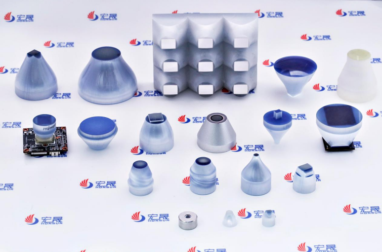
Your ideal taper ratio comes from dividing your required input field of view by your detector's active area dimension. That one number is a good first step for matching taper ratio to your system. But do not stop there. Check that ratio against two hard limits: resolution and light collection. A ratio that fits the sensor can still blur fine details or give the detector too little light. A tapered fiber either concentrates or spreads light, and that change affects both image sharpness and signal strength. This guide shows how to find the starting ratio, test it against real needs, and change it when trade-offs appear.
Key Takeaways
· Find your starting taper ratio by dividing the input field of view you need by the active area size of your detector.
· Compare your ratio with the limits on resolution and light collection to make sure it fits what your application needs.
· Higher taper ratios give you a wider view, but they lower resolution and let less light through.
· Lower taper ratios give you a sharper image and make it easier to line things up, but they also make your field of view smaller.
· Use a six-step checklist: measure the detector, set the field of view, figure out the ratio, check the resolution, test the light, and make sure it fits.
Tapered Optical Fiber Ratio Basics
The Taper Ratio Formula
Taper ratio shows how much a tapered fiber makes an image smaller or bigger. You find it by dividing the input diameter by the output diameter. A 4:1 taper turns 4 mm at the input face into 1 mm at the detector. That is demagnification. The same idea works the other way for magnification. The most important physical parameter is the ratio of the taper end diameter to the base fiber diameter. Manufacturers write this as a simple number. A 2:1 tapered fiber takes a 2 mm input and gives a 1 mm output. A 3:1 tapered fiber takes 3 mm down to 1 mm. You will also see taper ratio written as R = exp(−ΔL/(2L)), where R is the taper ratio and ΔL is the total elongation. That formula describes how fiber tapering changes the diameter along the length. For most selection work, the input-to-output ratio is the number you need.
Why Matching Starts with the Detector
Your detector sets the limit. The output face of the tapered fiber must match the sensor active area. If the output is too large, light lands outside the active area and you lose signal. If the output is too small, you waste sensor area and lose field of view. Start with the detector dimension. Then work backward to find the input size you need. This approach gives you a matching taper ratio that fits both ends of the system. The waist diameter of the taper — the narrowest point — must line up with the sensor. Any mismatch at the waist creates vignetting or dead zones. You also need to think about core/cladding diameters. These dimensions affect how light travels through the tapered fiber and how much reaches the detector. A tapered optical fiber with the wrong core/cladding diameters will not couple efficiently, no matter how well the ratio fits. HONSUN's tapered optical fiber components are designed for precise input/output dimensional control. You can review their Fiber Optic Taper product line at https://www.gz-honsun.com for standard and custom options. The company builds tapered optical fibers with tight tolerances on both the large end and the small end. That precision matters when your detector has a small active area. A few microns of misalignment at the waist can shift the image and reduce resolution. HONSUN also produces fiber-optic components for image intensifiers, CCD coupling, and display systems. Each application demands a different balance of ratio, length, and numerical aperture. The basics stay the same: match the output to the detector, then verify the input fits your field of view. Once you have that starting ratio, you can check it against resolution and light collection limits. Those checks will tell you whether to keep the ratio or adjust it.
Matching Taper Ratio to Application Drivers
Imaging and Camera Coupling
Your application sets the ratio. For imaging, find the starting ratio with TR = input FOV / sensor dimension. Say your sensor is 8 mm wide and your field of view is 16 mm across. Then your starting ratio is 2:1. That ratio fits the sensor and still captures the whole scene.
Industrial camera coupling often uses ratios close to 2:1. A 2:1 tapered fiber makes the field of view appear two times larger. A 1.85:1 ratio can also work when coverage needs differ. These ratios balance field of view and resolution well.
For resolution-limited inspection, use TR ≤ object feature size / pixel size. If your smallest feature is 10 µm and your pixel pitch is 5 µm, keep your ratio at or below 2:1. A larger ratio would blur that feature over many pixels.
HONSUN's 2:1 taper ratio CCD coupling example uses 4 µm fibers at the small end and 8 µm fibers at the large end. This design lines up the output face with the CCD's light-sensitive area. It gives better coupling efficiency and sharper images. You can see this solution at https://www.gz-honsun.com/case/fiber-optic-taper-coupling-with-ccd.
Image intensifiers and medical imaging systems also use tapered optical fibers. These devices need precise control of input and output dimensions. If the taper ratio is wrong, the fiber will not match the intensifier's active area. The same idea applies to tapered optical fiber sensors in diagnostic equipment.
Tapered Fiber for Light Collection
Light collection follows different rules. Pick your ratio so the source image fits the detector. You also need to think about numerical aperture and etendue. Etendue is the optical extent of a beam based on both surface area and angle. In fiber optic devices, you find it by multiplying the fiber's numerical aperture squared by its area. Keeping etendue the same keeps optical power, which lowers losses.
Larger ratios focus light into a smaller area. But they can raise the output angle and lower collection efficiency. A 2:1 taper with input NA equal to the base fiber NA cuts throughput to 25%. That is the same as butt-coupling without a taper. A 3:1 down-taper on a 0.22 NA fiber allows a max usable launch NA of 0.073. Lower launch NA gives the best coupling efficiency.
Measured taper loss mainly depends on input NA. It does not depend much on taper length or fiber diameter. Matching the input NA is the key to getting the best collection efficiency.
Tapered fibers also help in refractive index sensing. A tapered optical fiber sensor can detect changes in the medium around it. The refractive index sensitivity of this sensor depends on the taper waist diameter. A smaller waist makes the refractive index sensitivity higher. So these sensors are useful for chemical and biological detection. Optical fiber sensors made from tapered fibers give high sensitivity in a small size.
HONSUN's Image Expansion Fiber Optic Plate works for seamless display integration with 1.1x–3x magnification ratios. This fiber-optic component removes visible gaps between display tiles. The tapered optical fibers at the plate edges push the input image outward. You can find more at https://www.gz-honsun.com/product/image-expansion-fiber-optic-plate.
For light collection, fiber optic sensors and tapered optical fiber sensors work better with careful NA matching. Your system's optics control whether light stays guided or escapes. A refractive index sensor based on tapered fiber technology needs the right ratio to keep signal strength. Whether you do imaging or refractive index sensing, the ratio must fit both the source and the detector.
Decision Checklist for Taper Ratio Selection
Choose a tapered optical fiber with these six checks. Start with the raw numbers. Then verify each one.
Calculate the Starting Ratio
First, measure your detector's active area. Use the same axis as your field of view. A CCD 8 mm wide needs a matching output face.
Second, define your field of view at the input face. A 16 mm scene needs a 16 mm input face.
Third, compute the starting ratio: TR = input FOV / detector dimension. Your matching taper ratio is 2:1 for 16 mm and 8 mm.
Your detector sets the limit. The output face must align with the sensor. The waist of the tapered optical fiber — the narrowest point — must line up. A mismatch at the waist creates dark edges. A tapered fiber that does not fit will not couple. HONSUN builds tapered fiber components with tight tolerances.
Verify Resolution, Light, and Fit
Fourth, check resolution. Your tapered fiber must resolve the smallest needed feature. Use TR ≤ object feature size / pixel size. Stay at or below 2:1 when your smallest feature is 10 µm and pixel pitch is 5 µm. A larger ratio blurs detail. Choose your imaging optics with care. A high-resolution tapered fiber keeps details sharp.
Fifth, verify light throughput. A larger taper ratio concentrates light. It also raises the output angle. Confirm your detector accepts that angle. Numerical aperture matching helps. Keep input NA low for your tapered fiber. A 3:1 down-taper on 0.22 NA fiber allows only 0.073 max input NA. A tapered fiber with too high an input NA leaks into the cladding.
Sixth, confirm mechanical fit. Formed tapers are 5–15 mm long. The practical limit for a taper ratio is about 5:1. Use a 1:1 length-to-diameter ratio for 1x–3x magnification. An overly long tapered fiber adds loss. An overly short tapered fiber twists the image. See HONSUN's catalog at www.gz-honsun.com.
Your optics — the lenses before the tapered fiber — affect the result. Contact HONSUN if you have doubts. Their engineers can review your detector and resolution needs. They will recommend a tapered fiber with the right waist, length, and NA.
Pick the taper ratio that fits your input field of view to your detector size. That one number begins your tapered fiber choice. Change it only when resolution or light collection causes a trade-off. A tapered fiber with the wrong ratio wastes light or makes details blurry. Go through the six-step checklist before you ask for a quote. Measure your detector. Define your field of view. Figure out the ratio. Check resolution. Check light throughput. Make sure it fits mechanically. Each step keeps your tapered fiber working well. HONSUN engineers can look at your detector and suggest the right tapered fiber. Their team makes tapered fiber parts with tight tolerances. Share your application details for personalized tapered fiber selection help.
Get personalized taper selection assistance
FAQ
How do you figure out the starting taper ratio for your system?
Take your needed input field of view and divide it by your detector's active area size. A 16 mm scene on an 8 mm sensor gives you a 2:1 ratio. This number is where you begin. Then test it against resolution and light collection limits.
What is the real limit for a fiber optic taper ratio?
Formed tapers usually top out at about 5:1. Ratios above that get harder to make and line up. They also cut down resolution and light throughput. Stay inside this range for steady results. HONSUN can help with custom choices at www.gz-honsun.com.
Does a higher taper ratio always mean better light collection?
No. A bigger ratio squeezes light into a smaller spot. But it raises the output angle and lowers how much light you collect. A 3:1 down-taper on a 0.22 NA fiber allows only 0.073 maximum input NA. Match numerical aperture to keep losses low.
How does taper ratio change image resolution?
A higher ratio lowers resolution for each object detail. The same feature lands on larger fibers at the big end and smaller fibers at the small end. For resolution-limited work, keep your ratio at or below object feature size divided by pixel size.
When should you call HONSUN for taper selection help?
Call HONSUN after you work out your starting ratio and check resolution, light, and mechanical fit. Their engineers look at your detector and what your application needs. They suggest the right waist, length, and numerical aperture. Get personalized taper selection help at www.gz-honsun.com.